|
archives
|
| 2004 - second half |
|
25 December 2004 Happy Christmas, or Holiday, or Solstice, or whatever fits ... CL |
|
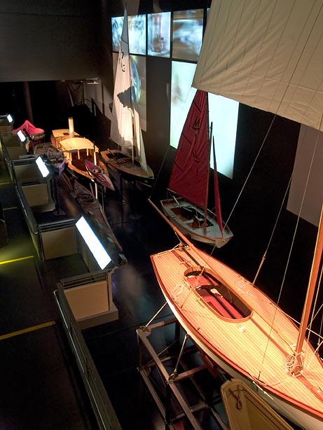
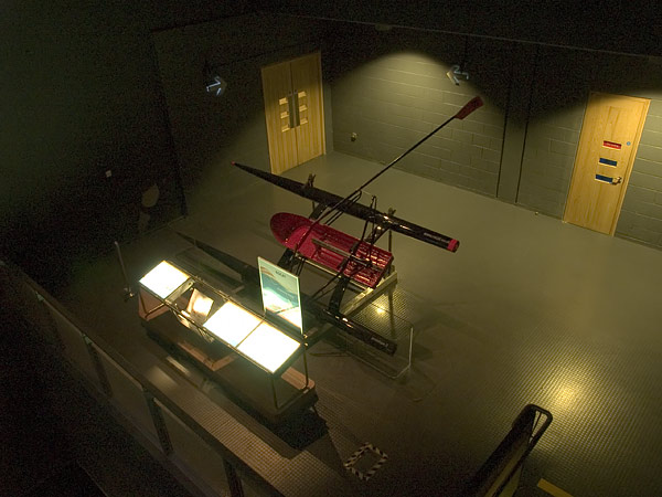
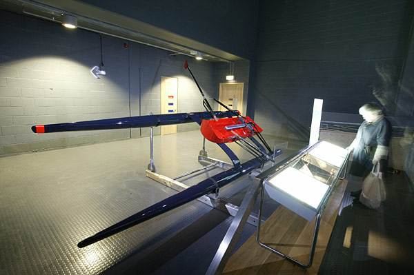
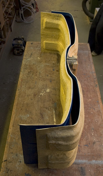
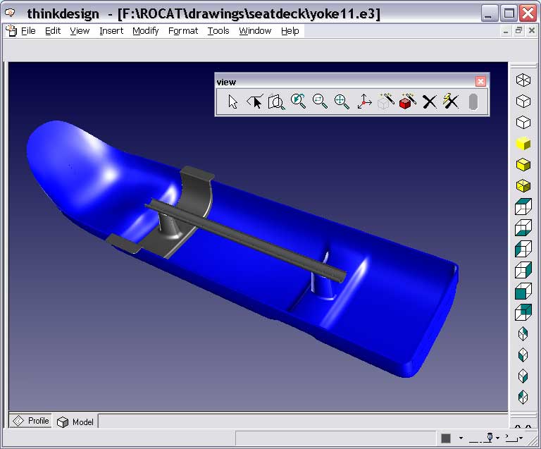
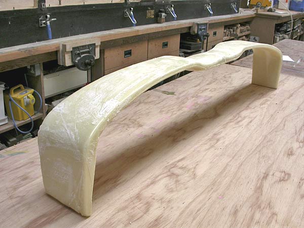
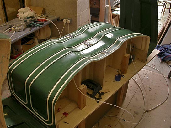
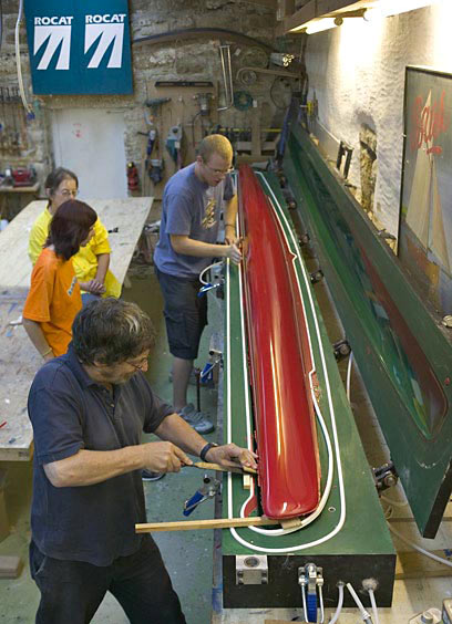
22 December 2004 The ROCAT prototype's tenure of '2004 feature boat' at the National Maritime Museum Cornwall in Falmouth is, sadly, coming to an end. It's been great to have the boat there and it has lead to a number of people getting in touch. For those of you who haven't heard of the museum, it is the new 'Small boats' outpost of the National Maritime Museum in Greenwich. Dramatic in design, and built and fitted to a very high quality standard, it is an asset to Falmouth and Cornwall. As you enter the museum, you pass some exquisite models of small boats from around the world, and then proceed up a gentle ramp past some famous small boats. There is a huge audio-visual display behind them (first pic) which tells the story of each in turn. The ROCAT is at the top of the ramp, just before you go into the museum proper. The last pic is of the light and airy main hall. If you haven't been to the museum, it is worth a visit, even when the ROCAT is no longer there. With the mould for the crossbeam foam blanks pretty well finished (first 2 pics), The design of the rowlock has exercised me from the start. I have always wanted the oar to be located precisely in all its movements but, if you think what it's doing, that's quite a tall order. However, I believe a solution has finally arrived! It is quite different from what you might expect (unless you already expect every ROCAT solution to be quite different!) and I'm not sure that it should even be called a rowlock (or oarlock in the US and Canada) ... I need to model it up and have a prototype machined to try it out. If it works as well as expected, I'll post some pictures. ... CL |
|
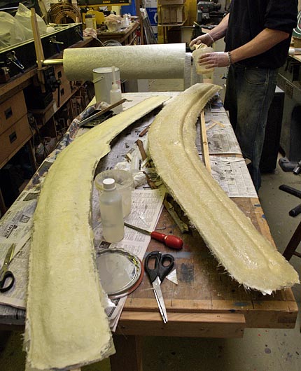
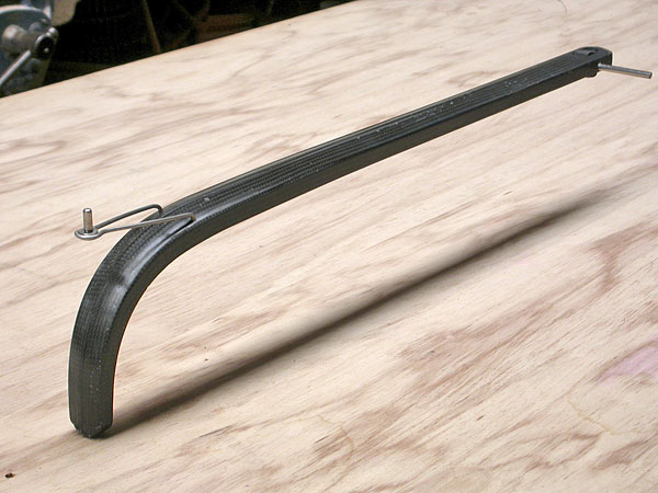
3 December 2004 It seems as though things have slowed down since we decided not to go to the Boat show, but our priorities have changed and the gain is more solid and less evident. Anthony has continued working on moulds for the footbar and crossbeam foam blanks. Although this is a time-consuming, somewhat convoluted process at this stage, it will save a lot of time in production. The boomerang-shaped things in the foreground of the picture below are the first sample footbar foam blanks – unfortunately, their thickness varies to much and they are not usable. Amongst other things, I have been working on modifications to the rowlocks and swingarm mountings in the light of our experience to date ... CL
|
|
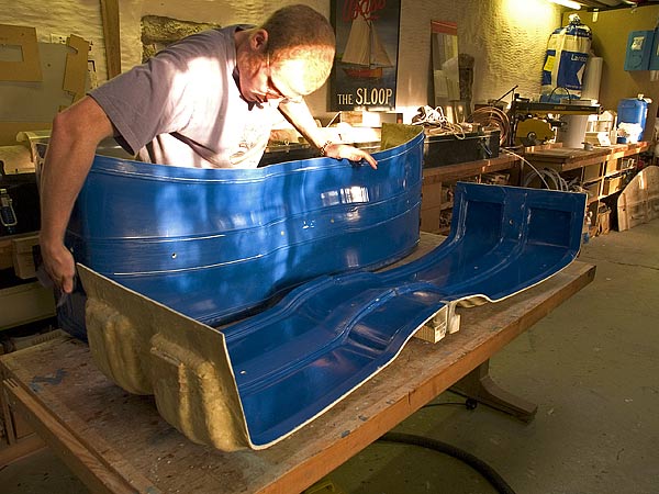
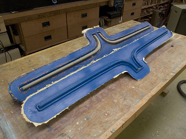
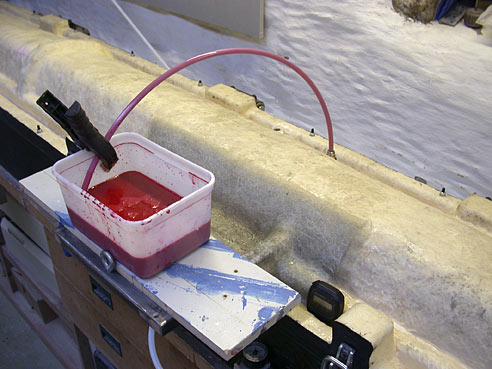
23 November 2004 Welcome to Regatta readers who have dropped in having seen out first, somewhat minimilist ad in that august magazine. We have been discussing safety ... starting from scratch, ROCAT is fortunate to be able to approach the safety issue without entrenched bad habits and attitudes. There is no question that the sea is a potentially hostile environment, but that's absolutely no reason not to play on it – you just have to be responsible and take the right precautions. The boat has a very high degree of 'primary safety' – it is extremely stable, and the very strong hulls each have 190kg buoyancy, with 100kg of built-in buoyancy in the unlikely event of the skin being punctured. But even so, we have decided to recommend the use of a gas-inflatable lifejacket at all times when rowing in open water... recent models are so neat, you hardly know you've got them on. We're going to provide one we like with the boat, and insist it The picture shows the crossbeam mould, with thickness wax, on the way to making the foam blank moulds. (Yellow and orange Plasticine was used to fill the seal grooves) ... CL |
|
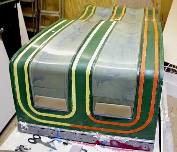
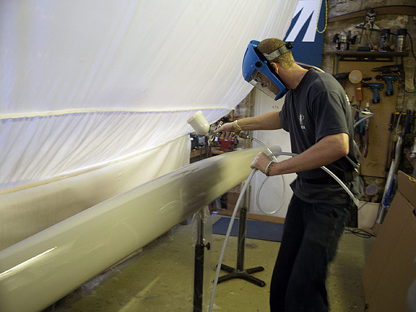
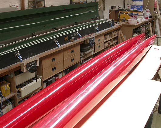
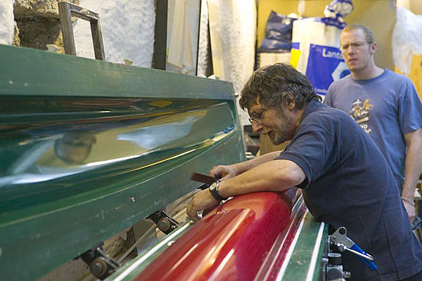
19 November 2004 With the pressure to get to the boat show lifted, it feels like we're back on track to produce the best craft possible - long term. In working toward producing a stunning looking ‘show boat’ I felt that we were having to loosen our grip a little, albeit temporarily, on one of ROCAT’s biggest assets; our attention to design and detail. We can now concentrate, once again, on doing all that is necessary to create what will be the most efficient and capable rowing craft in existence! Obviously we are still working very hard to get the boat on the market asap, but while doing so, we are also ensuring that it's innovative, effective, and durable. Our spray finishing system is looking very promising. The attainable finish is excellent and by spraying the primer into the mould we are eliminating many problems and reducing extra labour to a minimum ... AF |
|
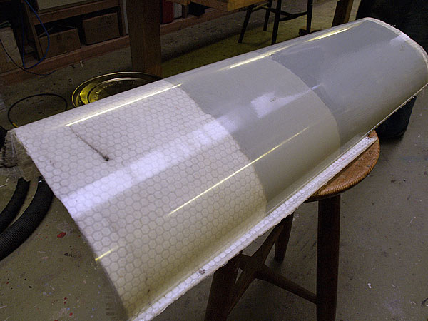
16 November 2004 We have decided not to have a stand at the London Boat Show in January. It would have been possible to get a presentable boat on the stand, but not without the burning of a great deal of midnight oil, and we believe our time would be better spent, at this stage, getting the boat ready for production. Anthony has been testing out the new spray equipment, and found it good. We have been experimenting with using a paint primer on the inside of the hull mould before laying up the glass. Normally one would use a gelcoat. The test panel was painted with epoxy, acrylic and no primer. While the epoxy primer released very cleanly, the acrylic paint was more difficult to demould. The third picture shows moulds Anthony has made for making foam blanks for the footbar ... CL |
|
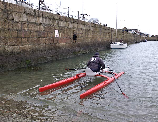
3 November 2004 Got back out today after some turbulent weather recently. Stiffening measures, while not pretty on this prototype, have worked well and the boat begins to feel the way it should. We have also begun to experiment with skegs to improve directional stability – there is an immediate and definite improvement to the way the boat handles. We will try different sizes, and then work out how to mount them! Unfortunately, they prevent the easy 'push off and jump in' launch procedure because the skegs then have to carry all your weight. They will either have to be strong fixtures, or reliably self-lifting. ... CL
|
|
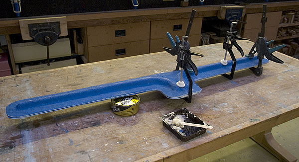
26 October 2004 As the picture above will testify, the old prototype was strong enough to go out in almost anything ... we haven't got to that stage yet with proto 3, and the weather on Friday was too wild to go out. Anthony has been applying 1 mm 'thickness wax' to the footbar mould. We are going to make 'foam moulds' for the footbar, swingarms and, probably, the crossbeams. The foam blanks (which come out of these moulds) have to be smaller than the mould cavity to allow room for the carbon fibre. You achieve this by lining the mould with special wax of known thickness, which corresponds to the thickness of the carbon. The third picture shows the seatdeck mould which has had the front track support post removed. This will be integrated into the new carbon yoke. Meanwhile, I have bought some spray equipment and discovered some very special paint. 'House of Kolor' paints have been developed for the custom car market in the States and they have some truly gorgeous colours. I think we will probably offer the ROCAT with, perhaps, half a dozen standard colours or, as an option, a free choice of colours from the HOK range. Another steep learning curve and so little time! ... CL
|
|
20 October 2004 Anthony has repaired the 'car' that carries the wheels for the footbar to roll up and down the track, so we will probably get on the water again on Friday. He has also 'deleted' the front track-mounting post from the male and female seatdeck moulds,
|
|
17 October 2004 I'm tired of the grammatical gymnastics that are often required to de-personalise these reports and avoid the first person – after all, there are only two people who could be writing them! Henceforth, I'll get Anthony to contribute more and we will attach our marks. We've used this week to re-group; to clear up the workshop, (begin) to tidy my office and deal with a hefty backlog of paperwork. It's been great to get proto 3 on the water, and we've already learned some valuable lessons but, in among further testing, we must now focus on our next target, the London Boat Show. We will have one boat on the stand and, if the organiser's health and safety inspectors allow, one rowing up and down the dock outside the main hall. It is extremely unlikely that the general public will be allowed on the boat, but we plan to run demonstrations nearby, for those who are interested. We have had a radical rethink about the ROCAT's surface finish. The expert advice that I received when I was looking into every aspect of the manufacturing process recommended that I should avoid 'post-finishing' operations at all costs. The object was to take a perfectly finished part out of the mould. In order to do this, a coloured polyester resin gelcoat would be sprayed into the mould before laying up the glass This is standard practice in the manufacture of GRP boats but, the more we thought about it, the more we wondered whether it is appropriate in our case. Gelcoat spray equipment (which catalyses the resin at the nozzle) is very expensive; changing colours is a palaver; spraying polyester exposes you to the increasingly stringent styrene emissions regulations (that infusing epoxy avoids); strong, opaque, colours seem to be only available in a limited range of pre-mixed gelcoats; imperfections in the mouldings would be difficult to finish and, as customers will be able to choose their ROCAT's colours, production would be driven by the colouring process, so it would be difficult to produce components more efficiently in batches. So we began to look at painting. The downside is that it's another process and it takes up space. But, against that, it gives you so much more flexibility. If a hull comes out of the mould with a flaw (which really is possible in a real world) it is easy to fill and flat. You can make a number of hulls, and colour them on demand. The equipment is readily available and inexpensive. Colour changes are easy. Marine two-pack polyurethane paints seemed the obvious choice, but we were disappointed at the relatively small range of colours and finishes. We do need a paint that is very tough, but we don't need one that can sit in the harbour all summer in all weathers. So we then looked at two-pack acrylic automotive paints, and what a revelation. They are as tough as the marine paints but, immediately, you have access to a huge range of colours, and the possibilty of some interesting and exciting (optional) finishes. I will be getting equipped next week and we will begin to experiment. ... CL |
|
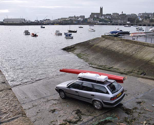
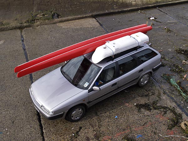
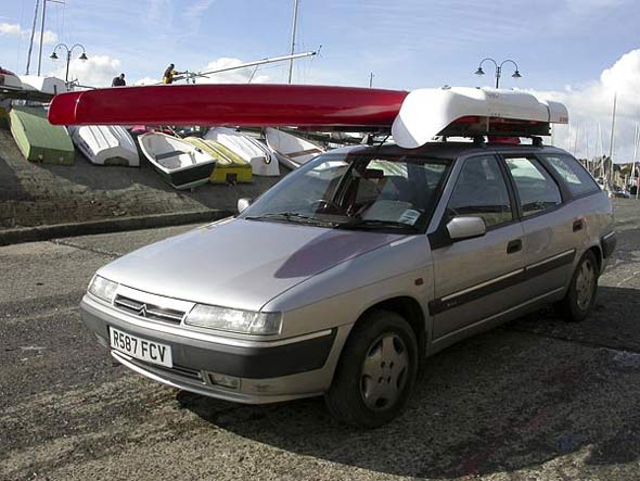
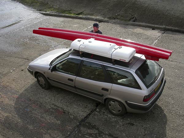
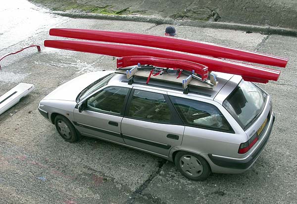
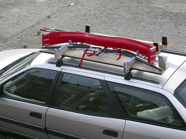
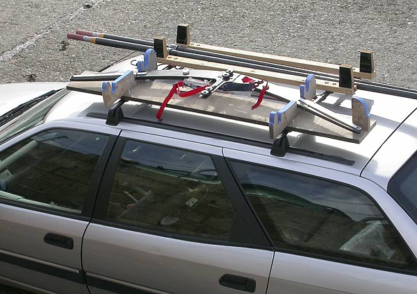
9 October 2004 Fitting the carbon yoke, and reinforcing the swingarms, has made a huge difference to the feel of the boat. The bottom swingarm bracket is still flexing a bit, but we're getting there – when that is stiffened, it will begin to feel as solid as it's supposed to. The pictures are of the car roof mounting system – we have been working out how to nest the main components to occupy as little space as possible. As you can see, it all fits pretty well under the inverted seatdeck. The production version will be a fibreglass tray fixed to the roof bars. This roof mounting system works fine on a regular, family-sized car with a longish roof, but how will it work on a small, or open-top car? Maybe we will have to develop Yesterday's session was shortened by a breakage – the stainless axle strip broke Regular visiters might notice that we have reverted to plain straps on the pedals for heel support – the other system worked, but proved just too complicated ... KISS!
|
|
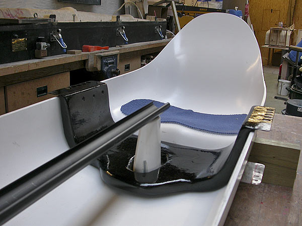
7 October 2004 We went out again, but the rigger arrangement is still too flexible. This is partly due to the swingarm itself flexing, and partly because the top mounting points are flexing the seatdeck more than anticipated – the seatdeck does have quite hefty carbon 'rails' along the top edge to resist these loads. We have fixed a stainless rod strut to stiffen the swingarm as a temporary measure, but it was decided not to try and reinforce the seatdeck. Instead, we will concentrate all the rigger loads into a separate, very strong carbon fibre 'yoke' to go across the seatdeck, between the swingarms. In true development style, Anthony knocked one up, yesterday, to test the principle. It doesn't look beautiful at this stage, but does feel extremely stiff. We will try it tomorrow. If we do go this route, the track support post will be integrated into the yoke moulding. Meanwhile, knowing that it would be impossible to make the ROCAT fit everyone, reliable anthropometric data was used to design the boat to fit the 98 percentile man and woman. Unfortunately, we have discovered that, in use, the track is too short for Anthony's legs! There was already an issue with the quality of the ends of the track,
|
|
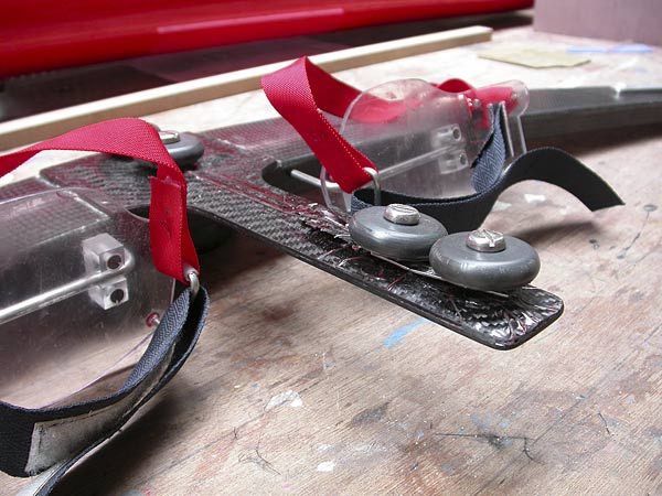
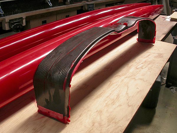
27 September 2004 Went out again on Saturday. Anthony had made a very strong U-shaped carbon-fibre 'yoke' to reinforce the seatdeck between the swingarms. This improved the stiffness of the seatdeck, but the swingarms were still too flexible, so they received an extra layer of carbon today.
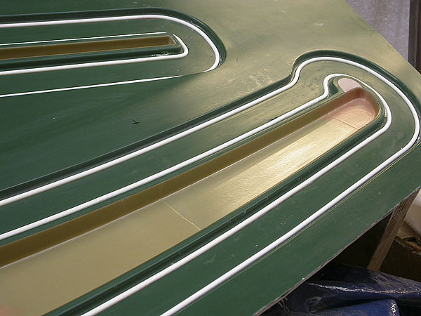
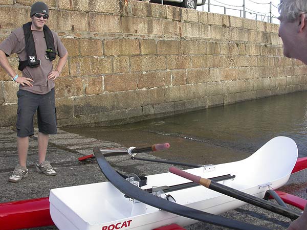
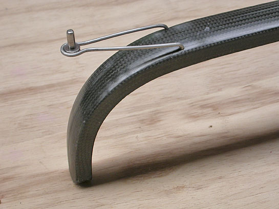
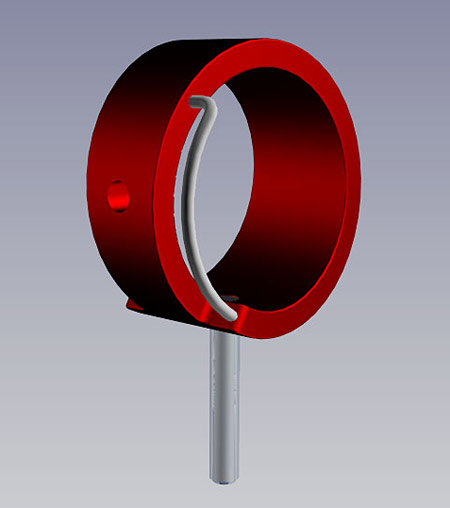
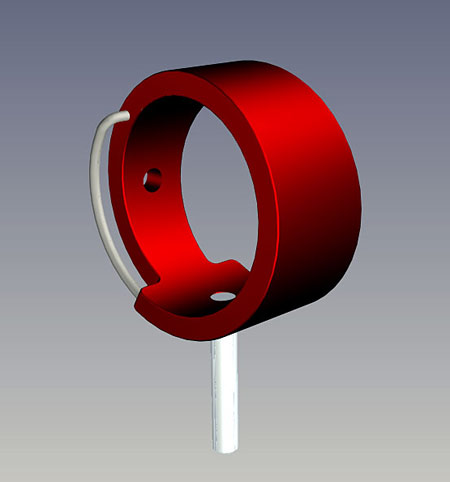
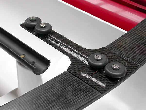
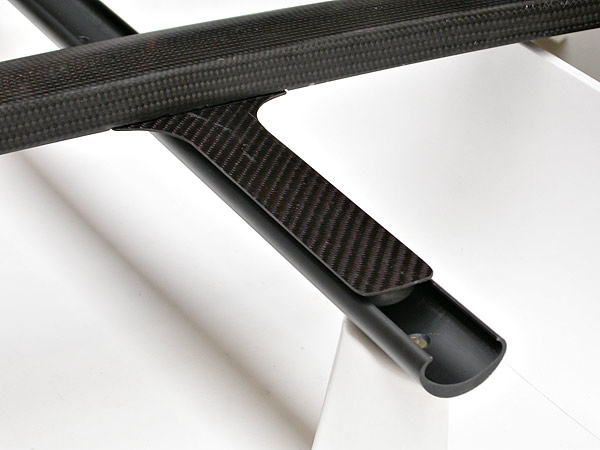
The picture shows proto 3's first rowlock – this isn't the final solution, but shows the idea. Unlike a conventional rowlock or gate, the ROCAT rowlock locates the oars precisely in all planes. One of the most important features of the ROCAT rig is that the rower's effort is transmitted, through the footbar and link strap, right into the centreline of the oar. A pin (which will be spring-loaded on the production boat) engages with a 'rotation limiter' which also renders the oar captive. The oar in this picture, BTW, is a dummy used for assessing best geometry and dimensions. |
|
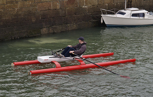
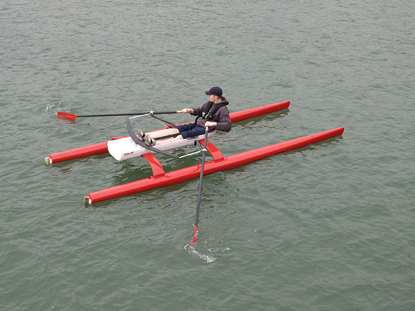
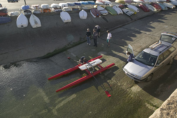
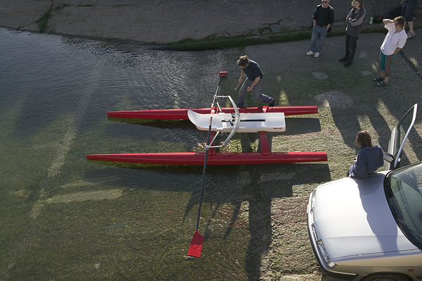
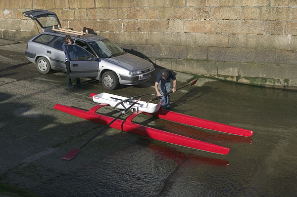
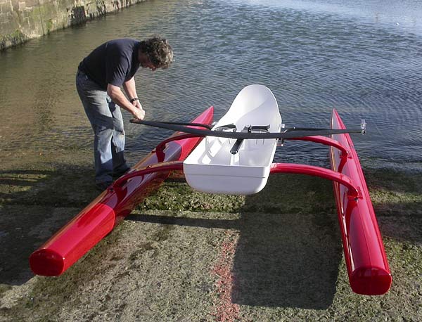
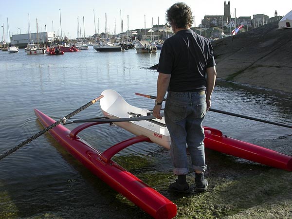
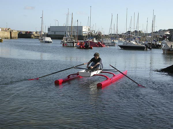
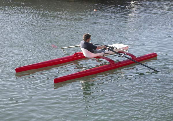
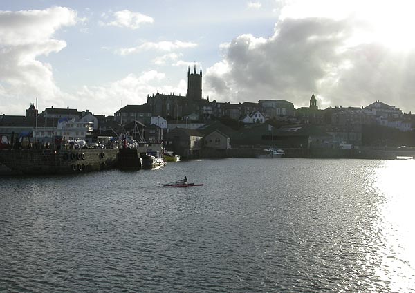
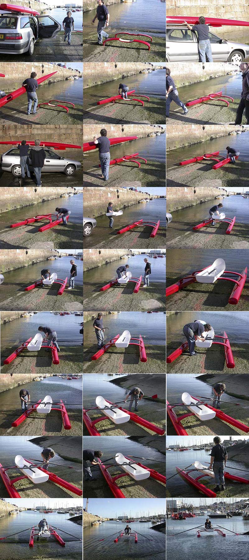
19 September 2004 The first ROCAT prototype, 'proto 1', was launched on 26 September 2000 – so it has taken almost 4 years to reach 'pre-production' prototype, 'proto 3'. As you can see from the pictures, we had perfect conditions for the launch of 'proto 3' and, except at very low tide, Penzance harbour is an ideal launch location. Christopher went out first and relished the improvements on the old boat. The seat back is now at a better angle and much more comfortable. And the rowlocks work better too – will post some close-ups soon, so you can see how they work. First impressions indicate that the bigger hulls make little difference to the speed, but the extent of the flexibility of the seatdeck is annoying – it means that the rowlocks, which are mounted on to the ends of the swingarm riggers (attached to the seatdeck), are too bouncy. The seatdeck between the swingarms needs to be strengthened. Anthony had a go but the flexing seatdeck made the swingarm pivots less secure than they should be, so we had to call it a day. We still have a long way to go before we have a bulletproof boat to take to the London Boat show in January, but it was fantastic to be back out on the water in a (proper) ROCAT.
This last thumbnail opens a 350K 'contact sheet' showing the launch sequence
|
|
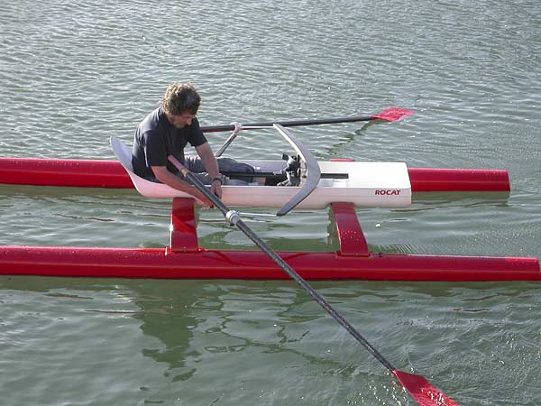
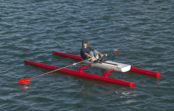
18 September 2004 Launched 'proto 3' today. Great to see the ROCAT afloat again; it's been a long time. The production boat is larger than the first prototype (to get more reserve buoyancy for the US market), but it doesn't really look it on the water. By the time proto 2 was retired, it was a hard-used lash-up – we haven't got everything right on the production boat yet, but the more sophisticated detailing does look good. In use, it was immediately apparent that the seatdeck structure, while strong enough, is too flexible ... will put up some pictures and commentary tomorrow. |
|
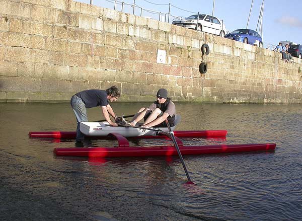
11 September 2004 We aim to launch the first 'pre-production' prototype (from the production moulds) As the day approaches, anticipation mounts. It's been almost two years since Christopher was last out on the original prototype, and he can't wait to see how the production boat compares; and Anthony can't wait to try it having been seduced to join ROCAT by the idea and the pictures you can see in the gallery! |
|
4 September 2004 The design of the swingarms, and their attachment to the seatdeck, presented some interesting problems. The rigger on the ROCAT performs an entirely different function from that on a conventional sculling boat. First, in order to define the arc described by the rowlock, it swings about pivot points attached to the seatdeck – the rigger animation illustrates why. Second, because the link to the footbar pulls the rowlock at the centre line of the oar, the swingarm only has to support the weight of the oar and none of the rowing forces. Third, the pivot point has to be adjustable along the length of the seatdeck to fit rowers of different stature. The carbon braid for the cross-beams has arrived so, on Monday, we will discover whether our proposed solution to the problems we have had making the cross-beams is effective.
|
|
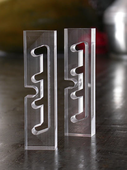
28 August 2004 Just received these from Falmouth College of Art (who are providing small-scale CNC machining services to industry). They are Perspex blocks which attach to the back of the pedals to provide vertical adjustment for the heel support. It will make more sense when you see it assembled. Here's a nice example of the advantages of modern technology, though ... it took me a few minutes to model this part in CAD on Wednesday afternoon and email it to FCA. They then machined it yesterday afternoon, and I got it in the post this morning.
|
|
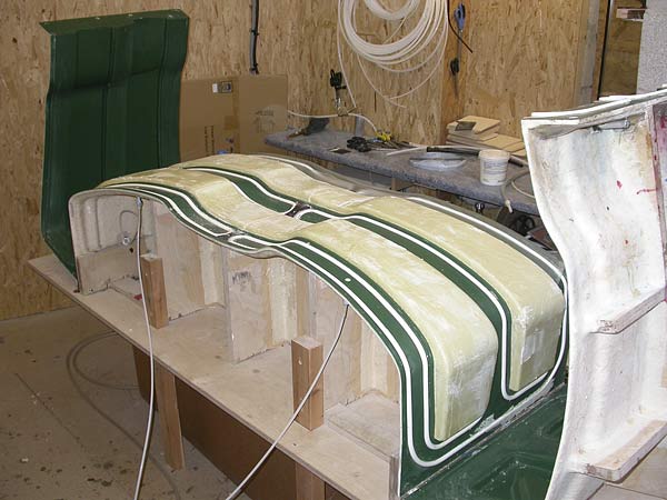
27 August 2004 Significant progress on the problematic cross-beams. We have used the cross-beam moulds to 'cast' two foam blanks using 2-pack polyurethane foam, with surprisingly good results. This is definitely not a production solution, but we wanted to try vacuum-bagging carbon fibre braid on to the outside of accurately shaped blanks. If it works well, we have found someone who can produce high-quality blanks from our moulds.
|
|
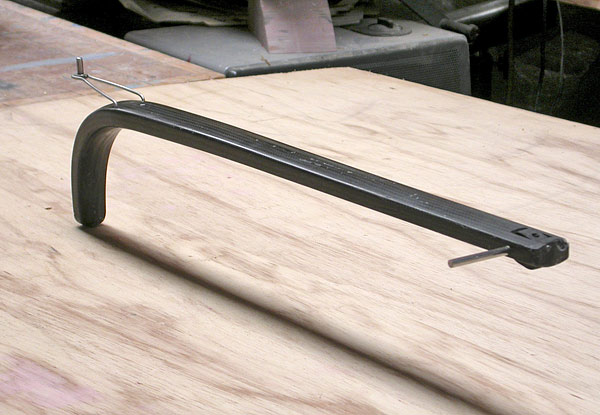
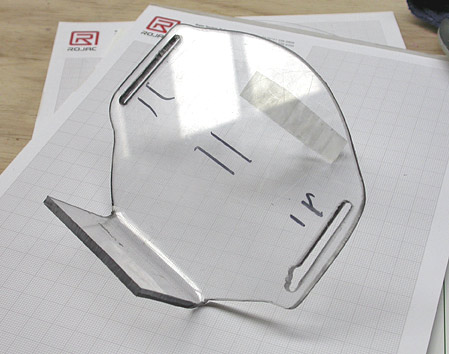
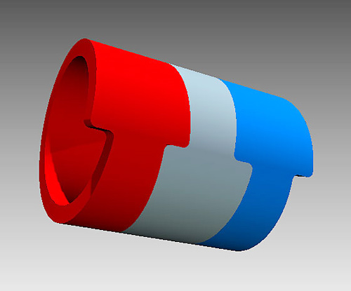
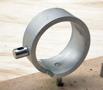
25 August 2004 Working on the pedals and rowlocks, both of which are very different from normal rowing boats. The pedals can pivot, like bicycle pedals – there will be a strap to hold your foot in place, and an adjustable heel support. The rowlocks provide positive location for the oars in all directions. The first production prototype was water-cut out of aluminium tube – the production version may be laser-cut. The oar is a close fit inside the ring. A spring-loaded pin engages with the wire 'rotation limiter' to limit the rotation of the oar to 85° – this device also renders the oars captive. Another particular feature of the ROCAT rowlock is that the rower's effort is transmitted, through the footbar, directly into the centre line of the oar, so there are no twisting loads on the rigger.
|
|
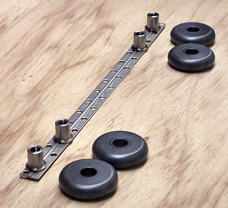
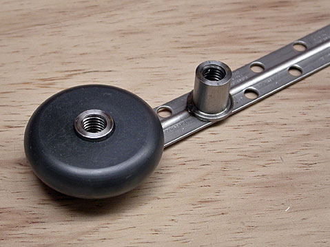
21 August 2004 We have laminated an axle strip into the first carbon fibre 'car'. The wheels are made of 'Vesconite' – a very hard self-lubricating nylon material which is used (amongst other things) for ships propeller shafts. The car is fixed to the underside of the footbar, and the wheels roll on the inside of the extruded aluminium track.
|
|
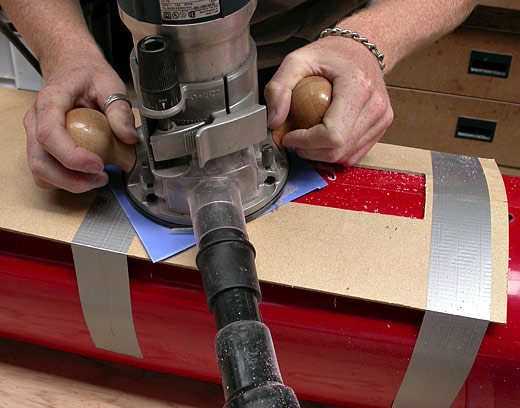
19 August 2004 Infused another hull yesterday afternoon, and popped it this morning. We applied lessons learned on the previous three, and this one is very nearly up to production standard. Impressed to find weight is within a few grams of hull #3. This time, we used the intended bag removal trick. A cord (inside the bag) is attached to each end – when the slots are cut for the sockets, the cord is simply pulled; the bag peels back from the ends and is then easy to take out. The slots for the sockets are cut using a router working inside a template.
|
|
13 August 2004 CNC-machining foam blanks for the cross-beams is not an option – too expensive. |
|
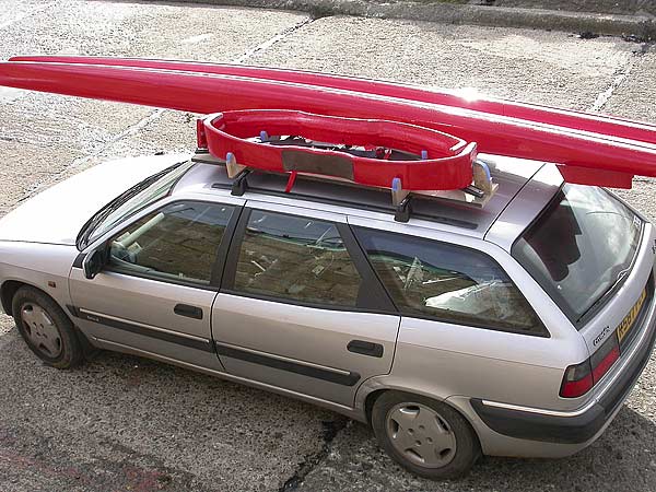
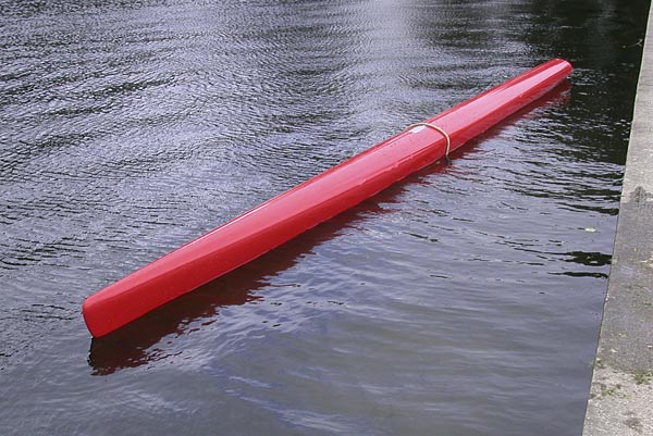
11 August 2004 Looking into having hard foam blanks CNC-machined for the cross-beams, instead of using a bag to make the shape inside the mould – it works well for the footbar, so may be the answer for the problematic cross-beams. Some may have noticed that the seatdeck has not been mentioned – this is simply because we got a remarkably good (perfectly useable), first pull from the mould. Took one of the hulls down to the Penzance boating pool to carry out buoyancy tests. Before we can cut slots to bond in the sockets, we need to establish the precise centre of buoyancy. We slung 55kg under the hull (which represents the design waterline with an 80kg person on board), and moved the sling back and forth until the transom just touched the water. It turned out to be just 20mm further back than the CAD model suggested. Anthony (who is about 100kg) wondered what would happen if he climbed on to the hull – as you can see, the ROCAT has a lot of reserve buoyancy! Once in production, the ROCAT will have a dedicated roof mounting system, but the pic below shows the size of hull on a regular family car.
|
|
6 August 2004 Demoulded the third hull this evening – were not at all sure how it would come out as we could hear air moving around inside the mould while it was infusing. In the event, it had infused OK and it demoulded very easily. It appears some air had got in where the bag pipe goes through the mould, but it had only left a few small voids in the skin. This moulding weighed a little less than the previous one at 8kg. Once the sockets are installed next week, we will have two usable hulls – which just leaves the cross-beams and some metal fittings to sort out before we can get this first pre-production prototype on the water.
|
|
5 August 2004 For various reasons, the cross-beams have presented us with the most problems. Had another unsuccessful attempt at infusing one today – not bad, but still not good enough. So far, we have only tried one cross-beam at a time but, once we have a reliable good part, the mould is designed to make both cross-beams in one go. Bighead in Bournemouth (who make metal fittings for manufacturers to laminate into composite parts), has sent a prototype 'car' fitting – the 'car' is what we call the part with wheels that attaches to the footbar and rolls up and down the track. Bighead has welded four wheel axles (very precisely) on to a stainless strip, which we will laminate into some carbon fibre to make the car.
|
|
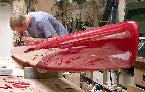
22 July 2004 Demoulded the second hull from new mould – this time the whole part infused properly and, although it's not cosmetically perfect, we do have a hull we can use on the first pre-production prototype. The 3rd pic shows Anthony cleaning off the flash. This moulding weighed 8.1kg, but we still have to add the cross-beam sockets (which we have already made), so will probably not quite make the target 8kg hull weight. The next job on the hulls is to carry out a buoyancy test to confirm the exact position of the sockets before we bond them in.
|
|
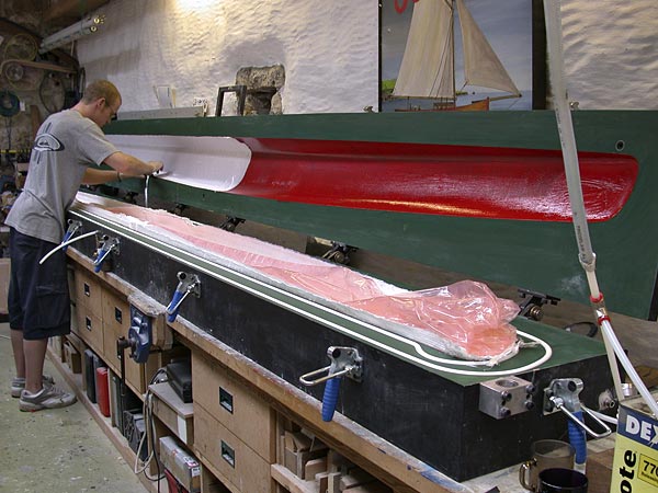
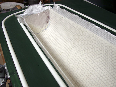
21 July 2004 Infused second hull from new mould. This time we used the intended layup of light high spec glass either side of Soric resin-infusion medium/core (which you can see in the second pic below). In the first pic Anthony is trimming the glass he has laid on to the gelcoat in the upper mould – you can see the vacuum bag in the lower mould. When the boat is in production, a machine will be used to inject just the right amount of mixed resin into the mould – at this stage, we mix the resin by hand and the vacuum pulls it through the reinforcement. Once again, the infusion process went smoothly.
|
8 July 2004 Replacement website goes live at last. People have been complimentary about the (difficult to update) old website which was done a long time ago using Flash. This new simple site will enable us to post regular updates on the ROCAT rowing catamaran's development. |